Historically, the 110V batteries located in the main locomotive have been the primary source of DC current for most railway applications. This meant that in order to light the individual carriages, it was necessary to run cables the entire length of the train.
Furthermore, since the battery was directly connected to the panel, the relays, and other heavy loads such as the starter motor, the voltage cables were regularly subjected to falls and transient peaks as well as electromagnetic and radio interferences (EMI/RFI). Passengers, on the other hand, remained unaware of such effects, except for occasional variations in cabin light levels.
Modern trains are much more technologically advanced than their predecessors and now include a range of safety features with multiple sensors and actuators. In addition, passengers benefit from comfort and technologies previously absent, such as air conditioning, wireless communication in addition to various infotainment.
Ensuring safety and comfort would not be possible without the presence of various energy sources that provide constant levels of DC voltage. remaining protected from external electrical noises. In this blog, we will explore some key features to consider when choosing dc-dc converters for railway applications.
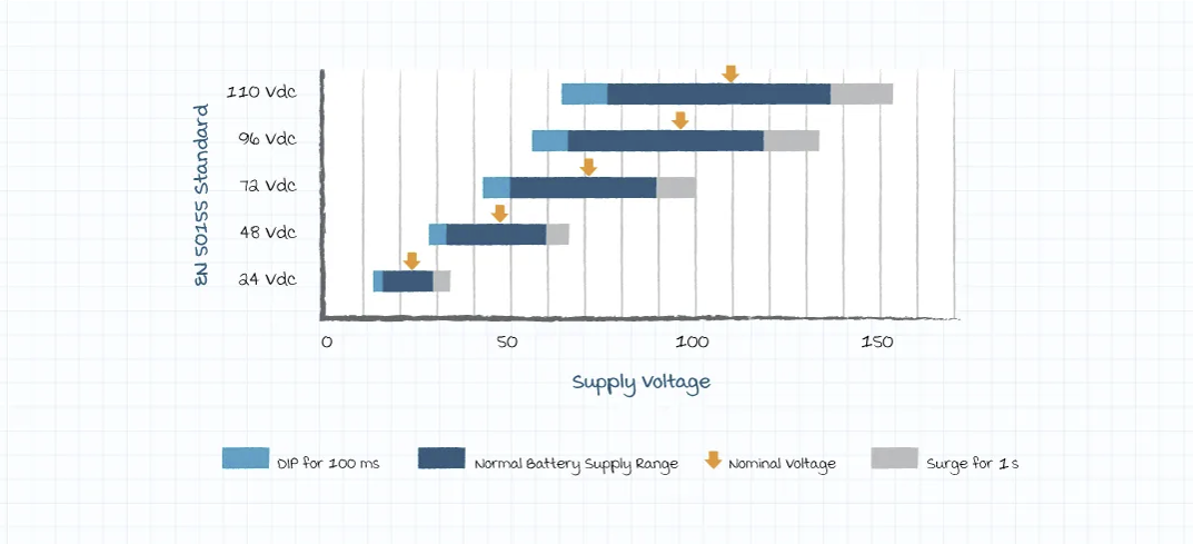
The certification EN 50155 for railway applications applies to all electronic devices serving the railway industry and has been adopted by most related manufacturing companies. It refers to battery-powered systems and low-voltage power supplies that are directly (or indirectly) connected to the system and cover the control, regulation, protection, and power supply of the system. All DC-DC converters must adhere to theEN 50155 in every form, according to the parameters listed below.
The most commonly used tensions in the sector are 24V, 48V, 72V, 96V and 100V. The inevitable drops and oscillations caused by devices in the system mean that these levels vary significantly. The EN 50155 certification specifies that ranges are allowed from 0.7 to 1.25 times their nominal value, with acceptable transient variations from 0.6 to 1.4 nominal (for durations up to 100ms).

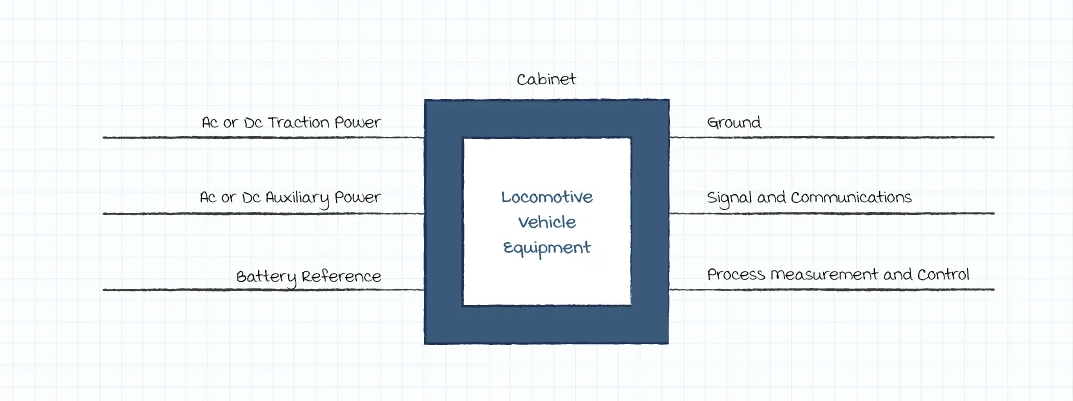
Electromagnetic compatibility (EMCThe demand for electronic devices is defined by how the instrument interfaces with the external environment. These 'interfaces' are known as ports. Different ports have different EMC requirements.

There are no emission limits for the battery doors in the frequency range from 9 kHz~150 kHz. The same EMC requirements apply to batteries, signals and communications, measurement processes and control ports and are specified in the EN 50121-3-2. The requirements for the immunity test are also specified in EN 50121-3-2.
All devices must necessarily be able to withstand the levels of shock and vibration to which a regularly scheduled train is subjected, without any loss of performance. These levels are defined by the service provider and in any case must comply with the conditions dictated by EN 61373 category 1, class B (table below).
| PERFORMANCE | EN50155 / IEC61373 |
|---|
| VIBRATIONS |
Category |
| SHOCK |
Long./Trans./Vert. axis 5g/3g/3g 30mS/30mS/30mS |
|
All electronic devices must be designed to work at the full range of their specifications within a range of different temperature classes.
The passengers and the driver are located in class compartments I'm sorry, but "OT1" doesn't seem to be a phrase in Italian or any language. Could you please provide more context or check if there's a typo? or As an AI, I need the text to translate from Italian to English. Please provide the Italian text. (with a standard reference set on the +77°F).
The classes OT3 and OT4 they refer to electrical panels (with a temperature of about +45°C).
The default class is the OT3.
| CLASS | TEMPERATURE RANGE IN °C |
|---|
| I'm sorry, but "OT1" doesn't seem to be a phrase in Italian or any language. Could you please provide more context or check if there's a typo? |
-25 - 55 |
| As an AI, I need the text to translate from Italian to English. Please provide the Italian text. |
-40 - 55 |
|
| OT3 |
-25 - 70 |
| OT4 |
-40 - 70 |
| OT5 |
-25 - 85 |
| OT6 |
-40 - 85 |
These specifications ensure that the conductors inside the power supplies have sufficient electrical insulation and enough physical space so that current leaks and sparks do not create problems. Specifically, this test is divided into two parts:
- A measurement of the insulation resistance set on the 500VDC. The minimum level of resistance required is 20 Megaohms.
- The second part is a test aimed at the resistance of the tension. The voltage levels are slowly increased (usually at 10-second intervals) up to the maximum value. The voltage is then maintained for a minimum of ten seconds to a maximum of one minute, depending on the type of test.
| VEHICLE BATTERY (V) | ISOLATION REQUIRED VAC(50Hz) / DC |
|---|
| 24 |
500/750 |
| 48 |
500/750 |
|
| 72 - 125 |
1000/1500 |
| 125 - 315 |
1500/2200 |
Check our category of DC-DC convertersTo find the model that best suits your needs or contact us to request further information, our technicians will be available to clarify any doubts you may have!


![How to choose the DC AC Inverter [GUIDA 2023] How to choose the DC AC Inverter [GUIDA 2023]](https://www.alimentatorishop.com/img/ybc_blog/post/thumb/MINIATURA-NEWS.jpg)


